I added a breadboard and LEDs to my Morse Code project (http://crashinginthecloud.com/2013/03/14/arduino-arrays-for-loops-switch-case-examples/)! It’s something I wanted to do since I first had the idea to create my own Morse Code parser on the Arduino. How will anyone Save [My] Ship if all I’m using is the tiny, built-in LED on pin 13?
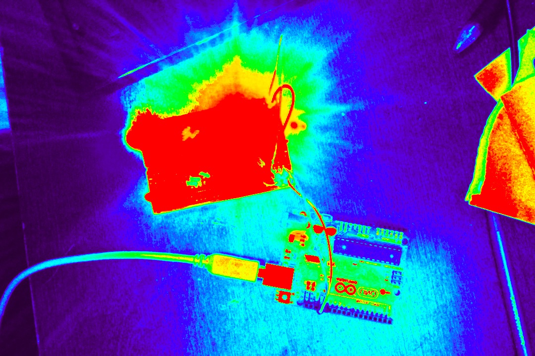
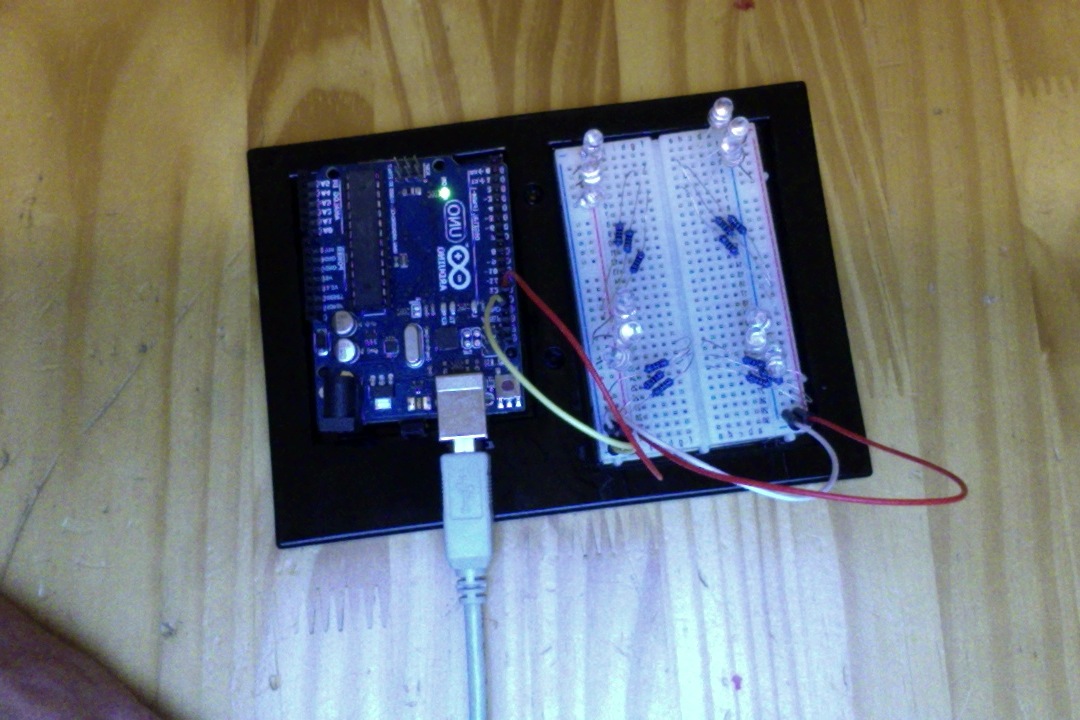
The final product uses 12 LEDs to flash the Morse Code encoded message instead of that measly old built-in LED. It didn’t require any changes to the sketch either, which was a bonus.
Before this project, I knew about breadboards, but I was really curious to find out how to use them to expand Arduino projects. This tutorial goes through a basic project that uses them.
First, I want to say that the tutorial at http://www.ladyada.net/learn/arduino/lesson3.html is really good (pictures, explanations, well written). That’s where I learned everything I needed to get this working.
Materials:
Ardunio Uno (I got my Arduino here – http://www.amazon.com/Starter-Kit-Newsite-Uno-Breadboard/dp/B0051QHPJM/; at the time I got it, buying the kit was cheaper than buying the Arduino itself, as far as I could tell)
Breadboard (came with the kit above)
4 jumper wires (also came with kit)
12 200ohm 1/4-watt resistors
12 LED lights (both the resistors and LEDs come in this kit: http://www.amazon.com/microtivity-IL184-Assorted-Resistors-Colors/dp/B004UZDKRG, and which came in the mail today!)
Here’s the rundown of how breadboards are used in conjunction with the Arduino:
1. Connect one jumper wire to an Arduino pin (1 – 13). Connect that wire to any of the holes in one of the positive columns. Now, any hole in that column is can be used as if it were the Arduino pin you plugged into. (Underneath the plastic, each hole in the column is connected to the others.)
2. To complete the circuit, connect a different jumper wire to a ground slot on the Arduino. Connect that wire to a hole in the negative column that is next to the positive column from step 1.
3. Connect one end of a resistor (doesn’t matter which end) to any of the positive holes in the same column you used in step 1. Connect the other end to a hole in any of the numbered rows.
Each hole in a numbered row is connected to all the other holes in that row. Anything else you plug in to that row will be connected to the positive column and, ultimately, to the Arduino pin.
4. Connect the positive leg of an LED (the longer one) to a hole in the same row as the resistor from step 3. One more step to complete the circuit.
5. Connect the negative leg of the LED to any hole in the negative column from step 2.
6. Repeat as many times as you’d like using different rows but the same columns!
7. I wanted more room, so I connected the other half of the breadboard to the circuit by connecting one jumper wire from the positive column in step 1 to the other positive column and doing the same for the negative column.